Tutorial
▀█▄ █ ▀█▄ █
▀█▄█ ▀█▄█
▀█ ▀█
Getting started with STM32: part 0, outline
Prerequisites: this tutorial series assumes you have some basic programming skills, and that you can code in C. Make sure you know what the stack, heap, and pointers are, as well as gcc, because they are very important for this tutorial.
Disclaimer: this tutorial will use the common STM32 Blue Pill (STM32F103C8T6) controller as an example.
Tools needed
- A STM32 microcontroller/development board, ideally the Blue Pill
- In later parts you will need an ST-LINK V2 Programmer
Preliminaries
So, you have an STM32. Congratulations! You're about to enter the scary and cool underworld of programming. So obviously, its time to get to it and start to write a program... but wait, how do you even start? I mean, what's the process? How do you even write code on this thing? How code even gets to the point it can run on this little microcontroller is not very self-explanatory, so to start, let's back up and take a look at the entire process as a whole before going in on building code.
For this tutorial, you actually won't use your STM32 at all. Go stash it somewhere safe... don't worry, the time will come to bring it back out and run a program.
Okay, so it's time to start. Before you do anything, you should go grab the datasheet and reference manual for your STM32. In most cases, the best place to look for these documents is on ST's website. Find your microcontroller (Blue Pill), go to Documents, and you'll see a lot of options. Try to find the Product Specifications section and the User Manuals section. You should find what you need there. While you're on the documents list, you should take the Programmer's Manual and save that as well. You won't need it for this tutorial.
This isn't a full tutorial on reading the datasheet (sorry), but you will have to use these documents sometimes during the tutorial to make sense of your microcontroller.
Okay, now that you have both of those, let's go through a little background info on your microcontroller.
What even is this thing?
The lines get pretty blurry when talking about CPUs, microcontrollers, microprocessors, System-on-Chips (SoCs), etc.
So let's focus on the actual setup of what you bought. Earlier I told you to stash your microcontroller away, but just for now, take it out and inspect it. Hold it in your hands. Feel the weight. Stroke it a little... oh sorry, I got a little carried away.
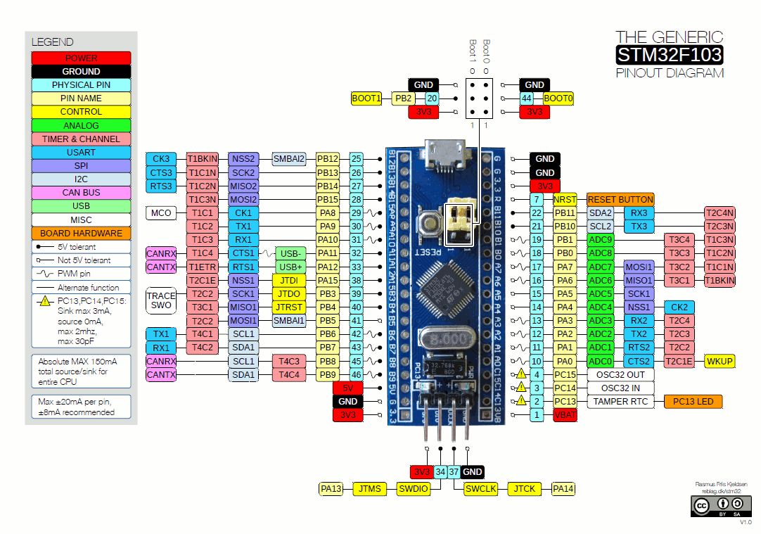
Source: Deep Blue Embedded
This is a Blue Pill.
A Blue Pill is actually a development board. The microcontroller is the little square in the center. In the real world, you won't see the entire development board inside a device. The boards are used for testing and learning (like you) before being installed. You'll notice that the microcontroller itself has a lot of little wires sticking out of it on all four sides. These are "I/O" or Input/Output. Signals are sent through these wires as different voltage levels (high and low are 1 and 0), used to communicate with the microcontroller. There are already some components connected to the microcontroller on a Blue Pill, such as a button labeled "reset", next to it are some jumpers, and USB-Micro-B above it. On the bottom we have a thing labeled "8.000", a little back square, and two lights below it. All these components are hard-wired to some of the I/O on the microcontroller.
The microcontroller itself has some rules for what types of components can be connected where. Luckily for us, we don't really have to know those rules, because the Blue Pill has connected all those wires already. Our Blue Pill doesn't really have many components connected to it, so most of the wires coming from the microcontroller itself are connected to those little holes you see on the left and right sides. In essence, the development board is just extending the little wires you see coming out of the microcontroller into a size that we can use. The diagram above is called the "Pinout Diagram", which helps us identify each wire (or pin). This is where we could add things like LED lights, motors, even other microcontrollers, you name it. The only rule is that it must be connected to a pin which actually does the thing you want it to do.
Actually, I was withholding the truth a little bit earlier. Not all of these pins are I/O. Some of them are used for powering the development board and the microcontroller. There are 37 I/O or GPIO pins on the Blue Pill and the rest are power-related.
As a little example, I want you to find the physical pin 20 and 44. I'm sure you can find them, they're on the pinout diagram.
Example: Learning about pins
What do these pins do, you ask? The answer is probably on our datasheet. That's scary, so let's look through it together. If you downloaded your datasheet from the ST website, it should look roughly like mine.
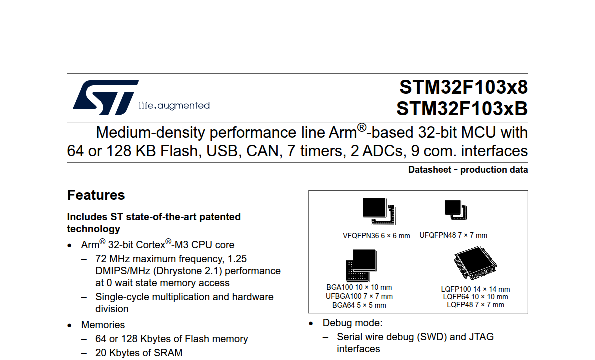
You can see that this datasheet actually covers multiple different STM32 models. In the name, an x represents any number or letter. This means that the datasheet works for our Blue Pill, the STM32F103C8T6.
These names are pretty odd, but there's pretty good resources out there for learning how the naming scheme is set up. I will leave it to those resources.
It looks like on the Pinout Diagram that the pins are named BOOT1 or PB2 and BOOT0. There's a pinout diagram in the datasheet, so let's confirm there. In the datasheet, move to the section called "Pinouts and pin description", or something along those lines.
Once you get there, you might recognize that a lot of the diagrams in this section look like they're referring to the pinout of the microcontroller itself, not the development board. It's a good thing we have the pinout diagram of the Blue Pill to make things easier for ourselves.
Scroll down until you find a table named "Medium-density STM32F103xx pin definitions" or, depending on your microcontroller, just any table called pin definitions. We're looking for physical pins 20 and 44, or BOOT1/PB2 or BOOT0. Here's one!
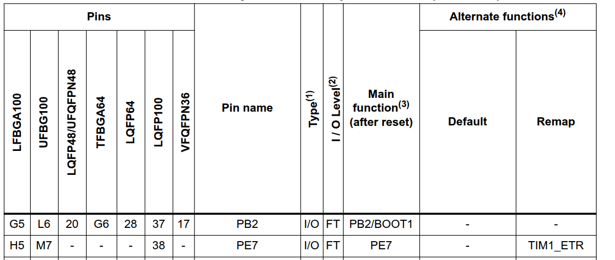
So it looks like there is a BOOT1. This table contains the pinouts for multiple package types, or different housings for the same microcontroller. The package types are the names you see on the left side. Intuitively, we can see that "LQFP48/UFQFPN48" has PB2/BOOT1 on pin 20, so one of those must be the package used by the Blue Pill. Every name has a number/letter associated with it, meaning that all of these packages have a PB2/BOOT1! Try to find pin 44 yourself.
Unfortunately, this table isn't very self-explanatory, at least for you right now. The package types don't really matter to us, and we still don't know what the pin does, besides that it is in fact an I/O pin and that it has something called an "I/O Level" of "FT". So we'll probably have to find what we're looking for somewhere else.
Unfortunately, a lot of these manuals and sheets are not really meant for hobbyists. Since industry is the focus, the datasheet won't bother explaining the high-level functionality or the context of pin 20 or 44. At this point, with some intuition, you could probably guess that it has to do with the bootup process of the microcontroller. But the actual functionality isn't self-explanatory.
As a matter of fact, we're actually going to have to know what these pins do in the future. So let's try to investigate further. This time let's look at the reference manual.
The reference manual is Big. The one by ST for the Blue Pill is about 1,100 pages. Sifting through this manually would be a mess, so you should just use an automatic search tool. I used Ctrl+F and searched "BOOT1", and found this pretty quickly:
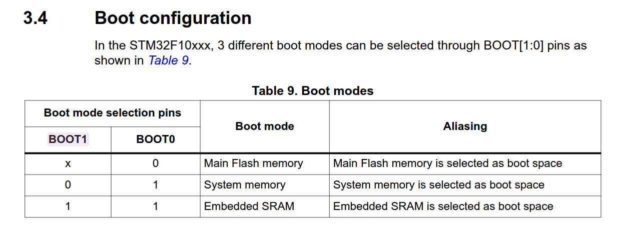
Great, so now we have a table of the functionality! If you scroll down, the reference manual has a description of how these pins and the boot process operates. Note that if you read the description, it might be difficult. As previously stated, these manuals are meant for industry.
Remember how most pins are called "I/O" or Input/Output? This means that they can both receive or send signals. In most cases, you can set them to either receive input or to return output in your code. Using some intuition, we can reason that this table describes what occurs when these pins are receiving either a 1 or a 0 during the boot process. So if the BOOT0 pin is not receiving any power during startup, the system will boot from Main Flash. Otherwise, depending on BOOT1, the system will boot from system memory or embedded SRAM. Remember that there were jumpers set up on the Blue Pill on these pins. Like a car, the jumpers allow you to route power from one pin to another. As you can see in the pinout diagram, it looks like the jumpers give us the ability to route power from a power pin to either or both BOOT1 and BOOT0. This means we can change the input on the pins between 1 or 0 during startup depending on how we place our jumpers. If you have a Blue Pill, try to take off the jumpers, looking at the label 1 and 0 next to the pins. They should already be placed at 0 and 0, meaning that we typically boot off of the Main Flash memory.
Okay, so now we've found the answer. If this is your first time with hardware however, the answer seems pretty confusing. What is Main Flash? System memory? Embedded SRAM? It's time to pivot back to a high-level view of microcontrollers.
Understanding your microcontroller
The point of a microcontroller is to run a program. While microcontrollers are general-purpose (meaning they compute many of the same instructions as general purpose computers do), they do not run an entire operating system like you are used to using on your desktop or laptop or phone. Instead of an entire PC, it's convenient to think of a microcontroller as a single program running on your PC. It exists in its own little bubble where it believes it is the only program and has all the memory to itself. On a microcontroller, that is ~pretty much~ literally the case. However, just like program running on an OS, there are things on a microcontroller that help it interact with things outside of this bubble.
To illustrate the point, let's recall how you output text to the terminal in a C program. Typically you could use the stdio function printf(), right? If you know a little bit about operating systems, you'll remember that printf() packages up the output data into a buffer (such as the string "Hello World") and uses a system call to politely ask the operating system to print the data. Similarly, I/O pins on a microcontroller allow us to communicate with other parts of a physical system through digital means (1 and 0s). The microcontroller itself, like stdio, also has some built-in functionality to assist with this process. However, unlike stdio, these functions are hard-wired.
As we've established, a microcontroller has quite a few I/O pins which are used to interact with the world around it through high/low signals, or 0s and 1s. At a high level, these pins read data into the microcontroller and output from the microcontroller so that the program running inside can communicate with the outside world. Oftentimes, this means flipping 1s and 0s coming off of/into a pin repeatedly, and the sequence of those flips represent the data, such as 0110001 or 01111010 (ASCII for a and z). At this point you might be asking a few questions: "How do we use these pins if we're just writing in C?" "Is there a standard for communication like there is between a program and the operating system?" These questions will be answered, but let's look at the details of the microcontroller itself first. (If you're curious about the second question right now, look up I2C and UART).
Memory: Flash vs. SRAM
Just like a program on your computer, a microcontroller needs memory. C programs which run on a microcontroller also have a stack and a heap, just like a computer program. If you've ever seen inside a computer, you'll remember that RAM (memory) sticks get connected on the motherboard. If you haven't seen these sticks, that's reasonable because they are pretty hard to find these days. Luckily for us, STM32s don't use the same type of RAM (DRAM). Although functionally used for the same purpose as DRAM sticks on a PC, the average STM32 comes with different SRAM sizes installed directly inside the microcontroller. SRAM is faster but less memory-dense (meaning less total memory for the size). The Blue Pill, for example, has 20KiB of SRAM which a running program can use to store data (such as the stack and the heap).
In addition to SRAM, the STM32 also has flash memory also embedded into the microcontroller. Again, like RAM, it is inside the microcontroller itself. Flash memory is non-volatile, which means that when the microcontroller turns off, the data does not get wiped like with SRAM. Because of this, flash memory is where you can store your program so it doesn't get deleted. This answers the question about the BOOT1 and BOOT0 pins: setting these pins to the default 0, 0 will result in the microcontroller loading any data located at the start of the flash memory as the first instruction of the program. The other options include embedded SRAM and System Memory. If you're currently wondering: "But what is System Memory?" or "Why would you want to boot from embedded SRAM if it should be reset when powered off?", we will answer these questions soon in later tutorials.
Okay, it's time to put everything together to answer some of the lingering questions. Take a look at this glorious diagram:
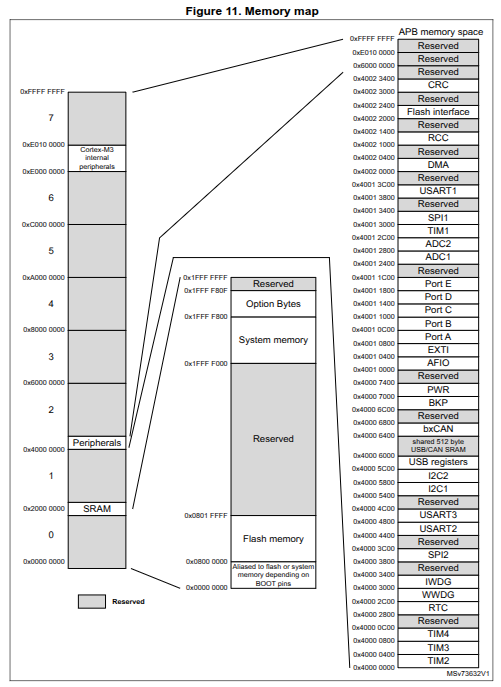
This diagram is the Memory Map for the Blue Pill. You can find this mapping yourself in the datasheet of your STM32. This might seem confusing, but we'll go through it.
ISAs, Memory, Addresses
Your little STM32 uses the ARM Cortex-M series as the base architecture. This is important to know, because the instruction set architecture (ISA) which the STM32 implements is based off of 32-bit ARM Cortex-M. You can learn more here.
Side note: If you're a bit confused by what an ISA is, I would recommend this video.
An ISA gives you the ability to perform actions on the CPU, such as add, subtract, bitshift, loop code, and more. These instructions are the building blocks of your code; it is what the C program you wrote gets translated to during compilation.
Yes, this is what assembly code is. We are about to briefly look at some. I promise this is not scary.
This is what 32-bit ARM instructions look like for a single function which increments a variable by 1:
int increment(int num) {
    return num + 1;
}
increment(int):
    str     fp, [sp, #-4]!
    add     fp, sp, #0
    sub     sp, sp, #12
    str     r0, [fp, #-8]
    ldr     r3, [fp, #-8]
    add     r3, r3, #1
    mov     r0, r3
    add     sp, fp, #0
    ldr     fp, [sp], #4
    bx      lr
It looks like a lot, and that's because it's doing what C does for you in the background: adding the num onto the stack, returning the num + 1 value, and removing itself from the stack.
I don't expect you to understand this code at all. You don't need to. Instead I wanted you to visually see the instructions that your C code gets turned into. str, add, sub, mov are all instructions part of the instruction set that the ARM 32-bit ISA uses to perform computation.
So, it would make sense that ARM also invented some instruction to be able to talk to your pins, right? Otherwise how else would you be able to send messages/listen through them?
Well yes, but actually no. The ARM ISA (and pretty much every modern microcontroller and CPU) uses a different method. This method is called MMIO, or Memory-Mapped I/O. You might be able to see where this is going at this point.
Remember how the ISA is 32-bits? This means that every instruction, such as add r0, r3, r3 does operations on data that is the size of a uint_32. So, add is actually doing add 0x00001543, 0x0003032, 0x0003032 for example. If we wanted to write a value to a location in memory using an instruction, we would have a range of memory spanning 0x00000000 and 0xFFFFFFFF, but we obviously don't have that much space in our Blue Pill. If each bit represented 1 byte, that would be 8*2^32, or 4GiB of memory. So, why not use that address space for something other than memory?
Instead of having special instructions to communicate with I/O pins, the STM32 has special locations in "memory" that relate to each pin. If you had a pointer:
*(void) USART1 = 0x40013800 and you type the C code *USART1 = 0xAAAAAAAA, for example (not how you would actually do this), on this specific spot in memory, you aren't actually storing a value in the SRAM. Instead, there's a little piece of hardware somewhere in the microcontroller which re-routes your instruction's data to the USART pin. Conceptually, this makes programming a lot easier, because creating an entirely new ISA for every single different microcontroller with or a model without a specific pin would be a nightmare for manufacturers and compiler developers. Additionally, it means that we can do the same thing for flash memory, too: just stick it in a new region in "memory" and re-route any writes to the flash when that memory address is used. As you can see in the Memory Map for the Blue Pill, flash memory starts at 0x08000000, SRAM at 0x20000000, and peripherals (I/O and such) at 0x40000000. Let's also start conceptualizing "memory" not actually as memory, but instead an address range between 0x00000000 and 0xFFFFFFFF. When you dial an address in this range, it will be sent to the home of whatever component lives in that address range. As you may be able to tell, some address ranges still are completely unused. If you try to dial them, nothing will happen (or you might have other errors occur, but we will discuss that later).
If you're still a little confused about Memory Mapping conceptually, I heavily recommend this video.
I was a bit dishonest here to get the point across. Actually, each pin has a few different settings—for example, you can't read and write from one pin at the same time, so you need to set it up to either only do read or write. So to set the settings of each pin, you first have to dial a location in the address space which will trigger the correct settings for the pin. Then you can begin to read or write from it from its location in the address range.
Let's look at the diagram again. As you can see in the memory map, many of the locations have a starting point, but no listed ending point. This is because different models come shipped with different sizes of memory. "Reserved" locations just aren't being used. Just looking at the Memory Mapping, it doesn't look like there are specific "pin" locations under peripherals, but I promise they are there, just hidden for now.
Before you leave
So far, this tutorial covered the preliminary things you need to know before programming on the STM32. If this felt like a lot of lecture and a lot of not-programming, that's okay. You'll get to programming soon. There's still a lot to cover, such as communication protocols, interrupts, different peripherals, and more. I hope this tutorial helped as a launchpad into the world of embedded.